Surface Quality Control for Maximizing LIDT in High-Power Laser Optics


In high-power laser systems, the optical components’ resilience to laser-induced damage directly determines performance, reliability, and service life. Even minor surface or subsurface imperfections can severely compromise the laser-induced damage threshold (LIDT), introducing failure points that limit system capability. LIDT limitations are a leading cause of component failure in high-energy laser systems. Internal testing has shown that a single high-absorption defect can reduce LIDT by more than 40%. With increasingly demanding power densities, ensuring the cleanliness and surface quality of optical components is necessary to reduce critical failures.
Surface defects limit LIDT
Microscopic surface and subsurface imperfections, such as scratches, digs, nodules, and bubbles, can form at multiple stages of fabrication of high-power laser optics, acting as precursors to damage. Although often microscopic, these defects can behave as local absorption centers or electric field enhancers, leading to damage far below expected LIDT values.
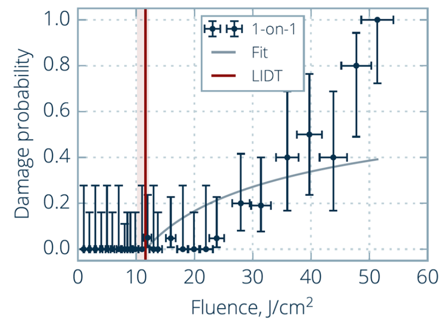
Figure 1 exemplifies the impact of defects on LIDT: a component reported a LIDT of ~12 J/cm² due to a single high-absorption defect site. Without that site, performance would have approached ~20 J/cm². As such, even statistically rare defects become critical in high-stakes systems.
Applications requiring a large beam size present challenging coating and surface quality requirements due to the increased likelihood of defects inducing damage. Beam size, therefore, plays a critical role in shaping coating design and surface quality specifications. Inertial Confinement Fusion (ICF) and direct energy laser weapons typically use beam sizes in a range of 10-40cm, making surface quality essential for such applications. Having information about the actual size of the beam or beams is critical for determining substrate quality grade and coating design.
Understanding LIDT: Measurement techniques and their relevance
Several standardized protocols exist for LIDT testing, including:
- 1-on-1 Testing (ISO 21254-1): Different sites are sequentially exposed to increasing fluence levels. This approach is simple and fast, but provides limited information on defect-related damage.
- S-on-1 Testing: The same site is exposed to increasing fluence levels until damage occurs, assessing cumulative damage over repeated exposures.
- Raster Scan Testing (LIDT Mapping): The optic is raster scanned at multiple fluence levels, generating spatially resolved damage maps. This method excels at identifying single-point failures caused by surface defects.
Raster scan testing is particularly useful when qualifying high-power laser optics for use in mission-critical applications, as it exposes local defect-induced absorption that other methods may miss. Its sensitivity to rare but critical defect sites makes it superior for real-world reliability assessments. For every new scan, the fluence is ramped up until damage criteria or the maximum available peak fluence of the test system is reached. Due to the discrete nature of fluence levels tested, LIDT is defined as the average of the fluence level at which damage has occurred and the next-lowest fluence level. The raster scan approach also tends to yield lower LIDT values compared to other methods, due to the likelihood of encountering defects that absorb laser energy and initiate damage [1].
Figure 2(a) illustrates the stages of damage under LIDT mapping, and (b) shows a raster scan measurement of an OPTOMAN laser mirror performed by Lidaris. In this example, damage initiation fluence level is at 8.9 J/cm² and catastrophic failure is at 22.2 J/cm².
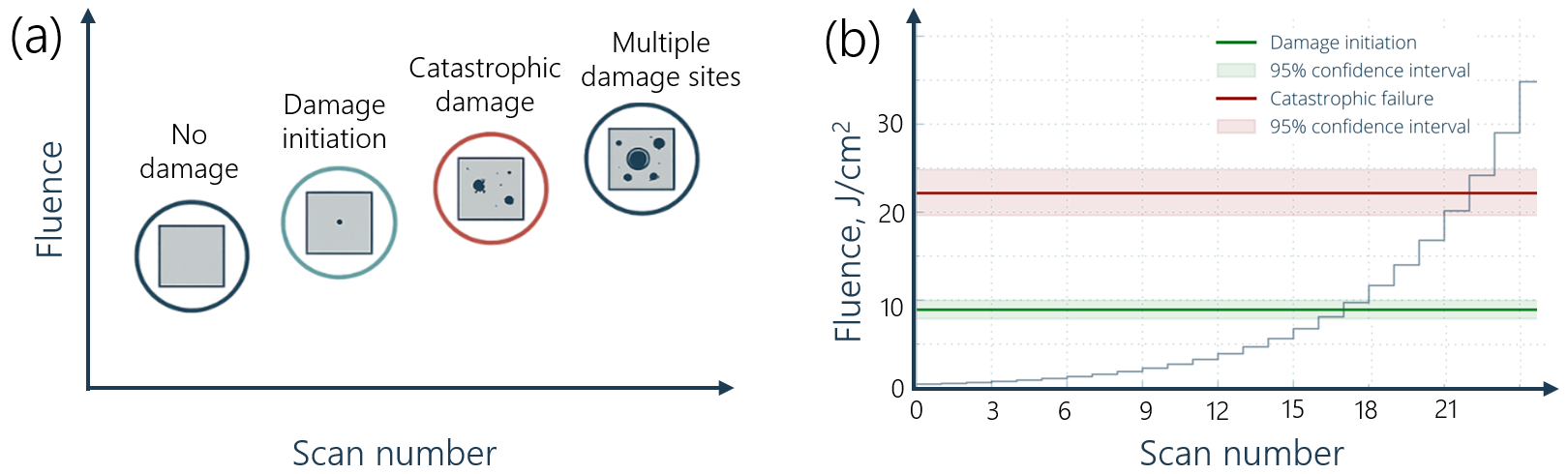
Figure 2: (a) Different stages of LID seen on a single sample scanned multiple times with increasing laser fluence, ranging from damage initiation at the first signs of surface modification, to catastrophic failure from cumulative exposure. (b) Raster scan measurement of OPTOMAN ⌀25.4 mm HR>99.95% @ 1064 nm laser mirror. 20% of the whole clear aperture was tested, dividing the area into 25 steps with increasing fluence levels. Measurement performed by Lidaris.
Laser-induced damage (LID) refers to the irreversible alteration of a material’s properties resulting from high-intensity laser interaction. This damage can manifest through mechanisms such as surface or bulk melting, material softening, bending, cracking, pitting, vaporization, or in extreme cases, catastrophic shattering. Once LID occurs, the affected optical component is typically rendered unusable.
Damage initiation occurs with the first observable physical change on the optical surface. While this initial change may not immediately degrade the optic’s performance, it often serves as a precursor to more severe damage under continued laser exposure.
According to ISO standards (e.g., ISO 21254 [2]), damage initiation is the reference point for most LIDT thresholds, especially in precision optics. Catastrophic failure, on the other hand, is more relevant when pushing systems to extreme conditions or evaluating damage resistance margin, i.e., the safety buffer from the operational laser fluence.
Defect detection with ARGOS matrix
Historically, the optics industry has used manual inspection for defect detection, which is prone to human subjectivity and depends on the availability of trained technicians. Computer vision-based defect detection has emerged as a more objective and consistent alternative, with the ability to provide detailed defect maps and statistics for additional traceability.
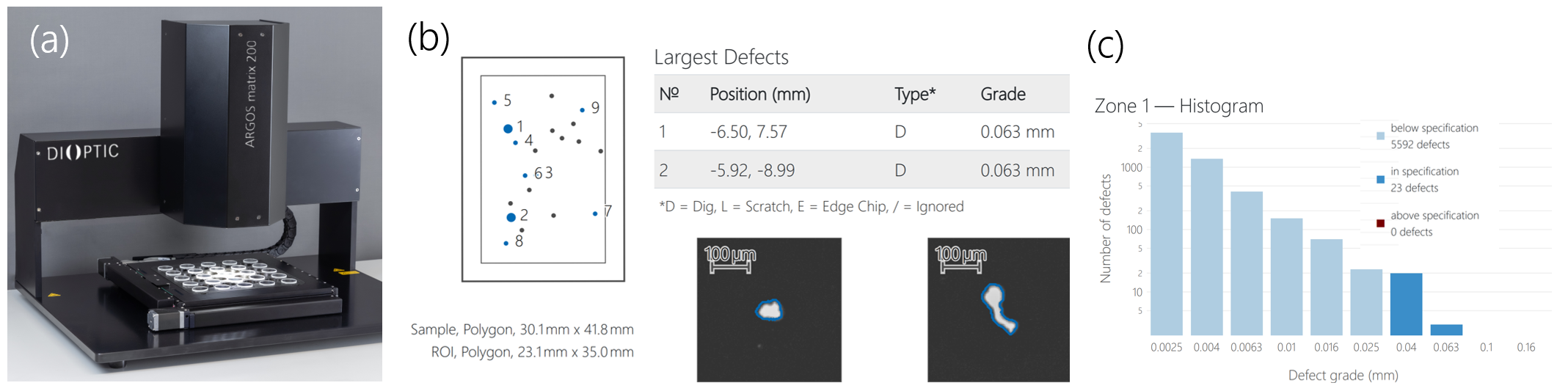
Figure 3: (a) ARGOS matrix 200 for automated scratch/dig inspection of optical elements. For each optic inspected, automated reports provide (b) defect maps with images of the largest defects and (c) a histogram of defect grades.
DIOPTIC’s ARGOS matrix system is an automated solution for defect detection that combines dark field imaging, conventional image processing, and machine learning to enable detection of defects as small as 1 µm on lenses or other optical elements. Figure 3(a) shows an image of the ARGOS matrix 200, and Figure 3(b) and (c) show defect maps, images, and histograms from the inspection report.
Defect types that can be detected via dark-field imaging include digs, scratches, surface contamination, particles, inclusions, and bubbles. All of these defect types have the potential to absorb energy under high fluence levels and induce damage. Defects are characterized according to ISO 10110-7 dimensional standards, meaning the width and length of scratches and the area of digs. Depending on the specification for surface quality, ARGOS software makes an automated decision of whether parts pass or fail the surface quality specification. Some ARGOS dark-field images of several defect types are shown in Figure 4.
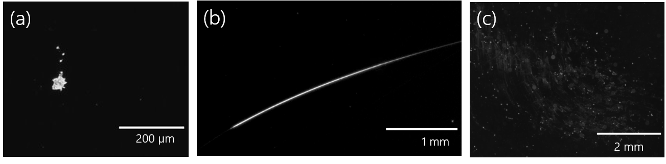 Figure 4: Example ARGOS images of different defect types: (a) dig (b) scratch (c) contamination
Correlation between defects, absorption, and laser-induced damage
An experiment conducted at OPTOMAN examined the correlation between detected surface defects and laser-induced damage. Coated samples with observable defects were tested using raster-scan LIDT mapping and are compared with the ARGOS defect map and an absorption map.
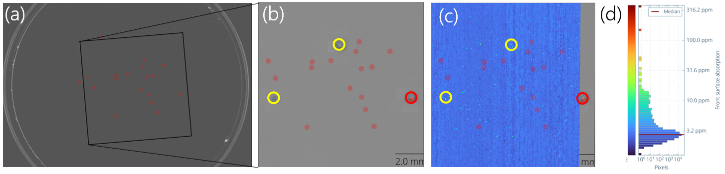
Figure 5: (a) Dark field image from ARGOS matrix inspection with the largest defects highlighted by red dots. The square region underwent LIDT raster scanning, with damage sites identified by circles in (b). Absorption map overlayed on ARGOS data (c), with the absorption map’s color bar and histogram in (d).
In Figure 5, the inset from the ARGOS dark field image in (a) shows larger defects highlighted in red. Figure 5(b) is an overlay of the LIDT map with three damage sites indicated by circles. The red circle indicates a damage site corresponding to a large surface defect (approximately 5 µm) and the yellow circles indicate the presence of smaller defects at the damage site. An absorption map is overlayed in Figure (c). Notably, the two highest absorption sites visible in (d) as above 100 ppm correspond to the two damage sites with small defects (yellow circles).
Interestingly, these results show that the largest defects are not always the first to induce damage, making defect size only one factor in predicting damage risk. The correlation between the highest absorption peaks and the damage sites highlights the important role absorption plays as a driver of thermally induced laser damage. Nodular defects that are present beneath or within the coating can create absorption peaks or act as micro-lenses, focusing incident light and generating localized electric field maxima. Some defect types, such as subsurface damage, may not be well suited for ARGOS detection and require additional metrology approaches.
All three damage sites contain surface defects detected by ARGOS, emphasizing the importance of surface quality analysis to reduce part failures. Since even small defects can result in absorption peaks that cause damage, minimizing the presence of such defects is critical for reducing the risk of part failure.
Automated inline inspection at OPTOMAN
At OPTOMAN, the ARGOS matrix system is an integral part of the quality assurance workflow for coated laser optics. This high-resolution surface inspection tool enables precise detection and classification of defects across the entire clear aperture of optical components. By integrating ARGOS into post-coating inspection, OPTOMAN ensures that even sub-visual defects that are likely to act as damage precursors under high-power laser exposure are identified. The system’s automated defect mapping and quantification capabilities ensure stringent quality standards and traceability for high-power laser optics.
Minimizing defects through process control
In addition to automated and objective quality control, ARGOS provides detailed inspection reports that enable coating engineers to develop tighter process controls and reduce part failures. Advanced optics manufacturers like OPTOMAN deploy tightly controlled processes to reduce defect probability, using the following techniques:
- Sputtering Coating Deposition Techniques: Sputtering coating technologies like Ion Beam Sputtering (IBS) produce coatings with fewer defects compared to evaporation techniques. This is due to a very dense coating structure resulting from huge particle energies used in the sputtering process.
- Coating Engineering: Layer designs that limit nodular growth and include in-situ monitoring minimize embedded defect risk.
- Cleanroom Handling & Packaging: Strict protocols from polishing through final inspection prevent particulate contamination, a known contributor to LIDT reduction. Minimizing dust in manufacturing and packaging areas is also essential.
Surface quality inspection can enhance process control. For example, ARGOS defect reports provide statistical tracking of defect characteristics and frequency over time to enable monitoring of manufacturing processes or the development of new processes.
Conclusion
Laser-induced damage might result from a single, undetected defect. Incorporating automated defect detection into the manufacturing process allows for early identification and inline part rejection. By combining robust LIDT mapping, advanced defect detection, and tightly controlled production processes, manufacturers can produce optical components that meet the durability requirements of high-energy laser applications.
This whitepaper demonstrates that combining OPTOMAN’s manufacturing rigor with DIOPTIC’s metrology expertise leads toward defect-minimized, high-LIDT optical components. This provides engineers and quality managers with the tools and insights needed to confidently specify and deploy reliable high-power laser optics.
Acknowledgments
We thank Lidaris for their valuable collaboration in performing LIDT measurements. Their expertise in laser damage testing has been instrumental in illustrating the importance of surface quality in achieving high-LIDT optical performance.
References
[1] R. Pakalnyte et al., “Laser-induced Damage in Optical Materials 2019,” Proc. SPIE 11173, 1117318 (2019).
[2] ISO 21254:2011, Lasers and laser-related equipment – Test methods for laser-induced damage threshold (LIDT), International Organization for Standardization, Geneva, Switzerland.